Pi Controlled
This is Part II of the frankenfeeder project. Part I is here.
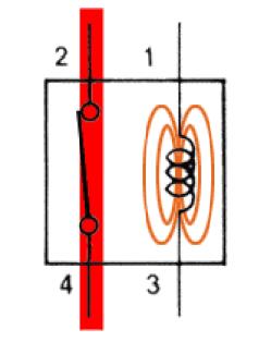 So how to close a circuit with a Pi. Simple, use a relay. A relay's job is to close (or open) a circuit when current is applied to it. (a nice illustration is here where I borrowed the image) So just pop a relay onto a PI GPIO pin and off we go right? Nope.
A couple things to consider first when switching a relay:
- A relay has to have enough current (Amps) to create an electromagnet that pulls a tiny switch closed. Pi pins just don't have enough umph. They have very little current.
- When an electromagnetic field collapses (when you turn off the current to it) it will send a spike into the system which can damage your PI. Ouch.
I happened to have a bunch of Aleph simple switch relays laying around from another project that failed or at least stalled indefinitely (I might write that up later).

These will work fine with the voltage and current from the 5V pin of the Pi, but not the 3V pin. So I needed a way to use the 3V pin of the Pi to switch the 5V pin from the Pi's power input. Again a little research payed off. I found this excellent article by Kevin Sangeelee on using transistors to do exactly that: http://www.susa.net/wordpress/2012/06/raspberry-pi-relay-using-gpio/. He even has a nice schematic.
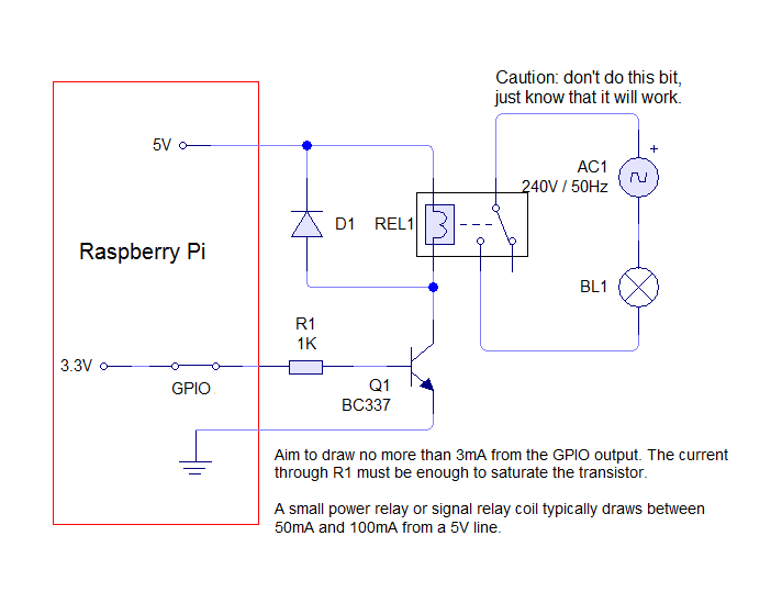 |
| Circuit to control a relay with a Pi GPIO pin |
Build the new circuit:
We needed more parts to build this circuit. As a matter of fact we needed two sets because we had to simulate pushing the two buttons at once. Here's the parts list:
- 2 - 2N3904 Resistors (Be careful to get the right resistors (normally off) and to make sure the polarity is correct. You can put them in backwards (like I did) and if you accidentally overdrive them (like I did) they will work, but they will require a lot more amps. Properly activated they should draw only 2mA (well within the PI's GPIO pin). So read the docs carefully (like I didn't).
- 2 - 1.2K Ohm resistors (I LOVE this handy guide)
- 2 - Aleph SD1A05AWJ relays (Digikey maybe, I forget)
- 2 - 1N4148 diodes (from sparkfun)
- 2 - Proto boards from sparkfun
We used google docs to draw up how to solder the parts on the proto board. The holes in the proto board are traced together in certain sections to make working with it easier. Here's the schematic we came up with and the finished board (one of them):
 |
| Relay Schematic |
 |
| Finished Version |
Now we had all the parts laid out to plug it all together. We did a bunch of prototyping and wiring the components up with alligator clips, jumper wires, and bubble gum. This site talks about the pins and their functions so we were able to wire up the 5V, ground, and two separate GPIO pins.


The long and short of it was that when we tripped the GPIO pins (how is in part III) Frankenfeeder came to life and rumbled around on the desk!!!! We had it prototyped. There was great rejoicing and much mad scientist cackling that was heard throughout the house.
The bits about putting it back together and how we controlled the pins etc are in Part III.
Would a MOSFET work in place of a relay? You could supply 3.3V from the GPIO to the gate, which would permit amps to flow from source to drain. It would be the binary on/off like a relay however.
ReplyDeleteI ask 'cause I really have no idea...
I meant to say the MOSFET WOULD NOT be the binary on / off of a relay.
ReplyDeleteA transistor or mosfet might do the trick. But I will claim ignorance. As I've discovered, I don't exactly understand the relationship between the gate and the drain completely. I didn't want to introduce any external current or signal on the existing feeder wires. As a matter of fact, I was guessing what was ground and what was a pin on the feeder pcb because the main IC chip was obscured with a blob of epoxy. The relay was not only handy but it gave this amateur the logical complete isolation between the controller (Pi GPIO) and the feeder PCB. Finally and most importantly, it got rid of any polarity question by simply being a wire that got connected and disconnected.
ReplyDeleteThank you Ben, I passed the first level!
ReplyDeleteNow, I have a problem to read how you soldered components on the proto board. Can you help again?
Thank you, thank you so much!
YAY!!! Great to hear Jeremy. Good work.
DeleteThe protoboard at the link above is a specific board with tinned holes and some of them are even connected. So I simply soldered the components on the reverse side of the board like soldering any through hole component. Those particular boards made it much easier by providing traces that connect several of the holes as shown in the Relay Schematic image above. Good Luck and I hope this helps.
Hi Ben,
ReplyDeleteThank you again for details.
On the schematic, I don't understand what do the blue lines refer to?
Also, on the photo, we can see a red wire besides the 1.2K Ohm resistor. Is it the connection to PI 5V?
Thank you!
Jeremy, The blue lines are jumper wires to link the traces together and complete the circuit. Yes, the red wire goes to the 5V pin on the Pi.
DeleteThank you Ben.
ReplyDeleteCan I use a big proto board (the one with you don't have to solder the components)?
I don't see exactly how to solder the components and prefer to test it before soldering components.
Thank you!
By all means! We used a breadboard to prototype the circuit before we moved it to the proto board. Use the schematic show above the proto board to model you breadboard.
Delete