Kick off:
A while back my folks moved to town in their retirement to be close to their mess of kids and grandkids. It's been great having them closer and in our daily life. My dad and I decided to spend a little time each week just geeking out with something completely unrelated to our jobs (he failed to retire properly) to rest our minds from the daily patterns. He is a pseudo-retired pastor and I do Cloud Computing. But we both enjoyed and wanted to learn more about hobby electronics or just making stuff.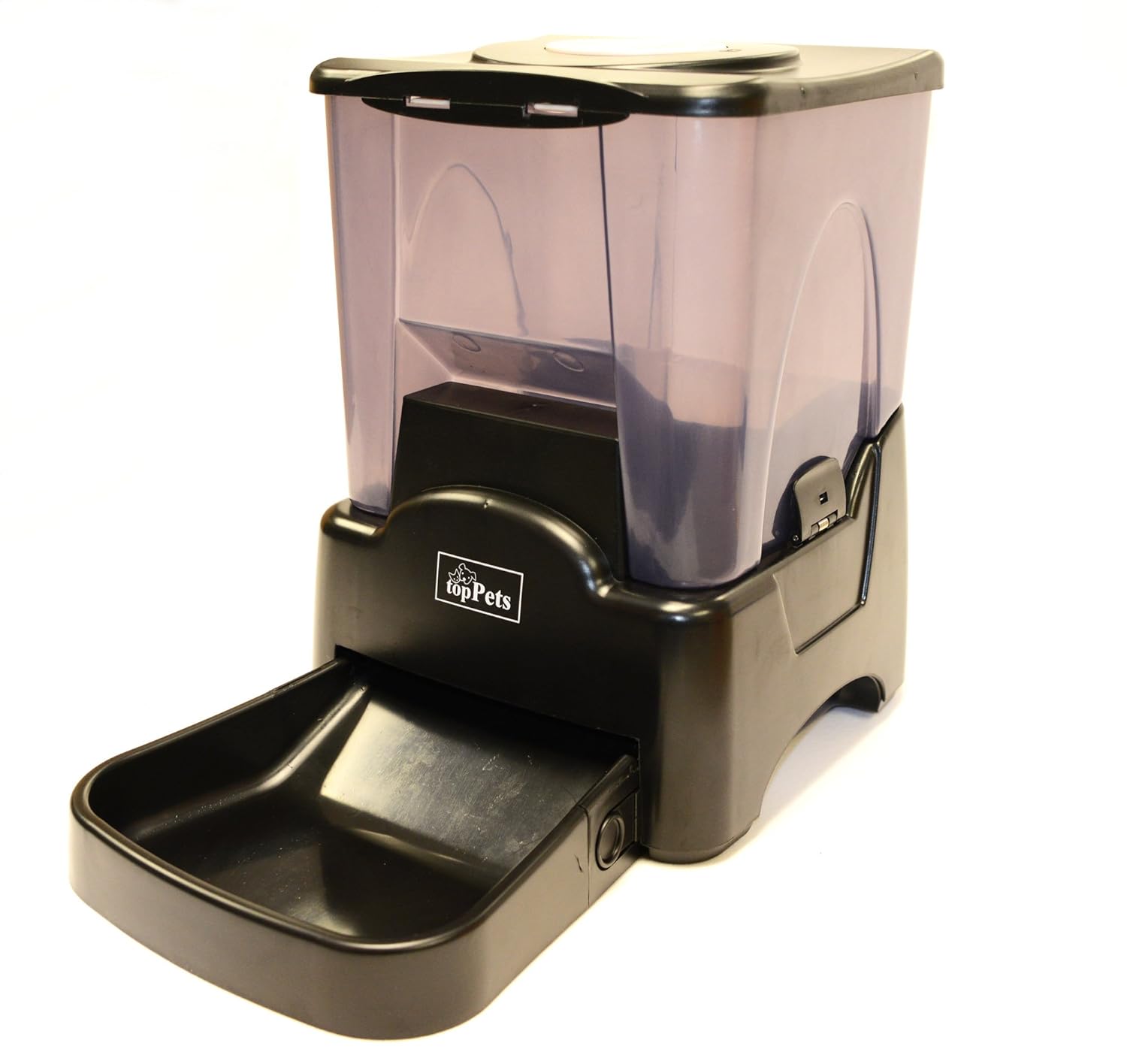 For our first project we decided to create something that would allowed my dad to feed his dogs remotely if he and my mom were out gallivanting (technical term) about. Don't worry, the dog door allows for the post-processing to occur safely.
We did some research and found this cool project by Amanda Ghassaei:
http://www.instructables.com/id/Twitter-Controlled-Pet-Feeder/
She had done a lot of the research already like finding a powered dog feeder and determining how to hack it to work on demand. Apparently, if you push the Volume and Set buttons at the same time it triggers the feed cycle. She shows how to connect to the board and use an arduino to logically push these buttons. We loved it, but wanted to add a few features:
- Wireless - put where the dogs eat, not where there's Ethernet
- Not twitter (giving my dad twitter would be like a giving a rubber boots to a fish)
- Feedback! Did it work and are the dogs happy?
- Inexpensive (cheap!)
- Ability to keep the manual functionality of the buttons
After discussing the arduino + wifi cost we decided that a Raspberry Pi + usb wifi would be much less expensive and possibly more flexible.
So the project parts list started like this:
- 1 - Rapsberry Pi (Get from your favorite reseller) aprox $35+shipping (a model A for $25 would work for this, but they weren't out when we did this)
- 1 - Automatic dog feeder
- 1 - USB Wifi dongle, Pi compatible
- 1 - USB Kodak S101 webcam (ancient, but pi compatible) I had laying around.
Getting Hacking:
We knew our first task was to disassemble the dog feeder and attached wires to the Volume and Set buttons on the PCB that controlled the feeder's manual feed function. Amanda's article had excellent pictures and instructions on how to disassemble the feeder and locate these buttons. But we didn't want to drill into the board as she described and possible eliminate the manual use of the buttons. So we followed the traces on the board to find spots where we could solder wires for each button and ground.

The first attempt failed miserably! The wire we used was so thick that any bump to the wire popped the solder joint off the board AND the heat of soldering to the spots we found, desoldered some surface mount components!! Fortunately the components were just zero ohm resistors and I could hack a wire back into place.
Take two had a better result. I apologize for not having a close up of the finished board, but we eventually traced each button and ground to simple, round, fairly isolated, copper pads. We used some magnet wire (enamel burned off at the ends) to solder to the pad to allow the flexibility we needed.
UPDATE: After requests for more details on where the solder points were on the circuit board, I borrowed a very nice close up image from Amanda's original project and highlighted the traces that we used. We soldered to the round pads you can see highlighted. The outer ring of the button contact was "common" and shared the yellow pad so each set of the relay boards described in Part II had one wire to the common pad and one wire to the red or green pad as seen in the image below.
We reassembled the feeder, leaving the leads handing out (we did remember to label them :-) ). Also we had to be VERY careful maneuvering around inside this feeder. It has very cheap construction and we accidentally knocked some wires lose a couple times from motors or PCBs. Nothing a little solder couldn't fix, but we learned to be extra careful.
UPDATE: After requests for more details on where the solder points were on the circuit board, I borrowed a very nice close up image from Amanda's original project and highlighted the traces that we used. We soldered to the round pads you can see highlighted. The outer ring of the button contact was "common" and shared the yellow pad so each set of the relay boards described in Part II had one wire to the common pad and one wire to the red or green pad as seen in the image below.
 |
| Close up with traces and pads highlighted |
Next task was to figure out how to ground the vol and set button leads when commanded from the Pi.
That's here in Part II
Hi!
ReplyDeleteThank you for your very interesting tutorial.
I live in France and I can't find the automatic dog feeder you talk about. Do you think this one will work : http://www.amazon.fr/PetFeeder24-H105-Automatique-Distributeur-Nourriture/dp/B0047JEBL4/ref=sr_1_2?ie=UTF8&qid=1377514400&sr=8-2&keywords=distributeur+automatique+de+croquettes ?
I precise that it doesn't have a LCD screen.
Regards,
Very good points you wrote here..Great stuff...I think you've made some truly interesting points.Keep up the good work. top pets automatic pet feeder manual
DeleteJeremy, Thanks. I hope it works for you. That link you posted looks very much like the same feeder. If you look at a couple of the pictures of the one we used, the screen and buttons are on the reverse side of the food dispensing chute. That may indeed be the same base unit, you just can see the screen. If there is a link to a manual you might check to see if it has a feed override button combination like the one we used. I highly suspect that it does and that it is the same one.
ReplyDeleteThank you very much for your help.
ReplyDeleteI will try to follow your tutorial now!
Nice hack! I had the exact same feeder.
ReplyDeleteWanted to do the same thing you did, but never did.
However, I did kind of 'hack' it.
Initially gave it a plug to run off of wall power instead of batteries, then added a button in front to manually run the unit (with the bump of a foot) instead of getting to the back of it and pressing 2 buttons.
Don't think I took any pics and I recently sold it in a garage sale as it's no longer needed.
Thanks Joe.
ReplyDeleteWe looked to getting rid of the batteries but wanted to simplify this project. A good future hack would be to replace the batteries and add a big honkin super capacitor so it wont loose settings every battery change or power flicker.
Hi Ben
ReplyDeleteI work in a School and the IT team are hoping to rework your fabulous project to build a native bird feeder for the Kindergarten girls. Any advice or thoughts on modifications?
Colin
Colin, that sounds like a really cool project. Are you planning on using the same feeder unit or finding something different for bird food. I ask because this unit could dispense seed if needed. I'll share some thoughts we had about the project in general.
DeleteThis particular feeder reset its brains every time the power goes out. Replacing the battery with a DC power supply would be something I would do differently. I would also look at adding a capacitor to keep the feeder pcb live if it underwent a quick power outage. Reprogramming the native feeder logic is a pain.
This feeder is very noisy when it dispenses as it intentionally vibrates to shake food down to the chute. If you are feeding sensitive birds a different feeder might be in order. Then again, it only makes noise when triggered.
As far as attaching wires to the feeder PCB, be very careful, there are lots of wires with cheap solder jobs floating around in the unit and we accidentally unhooked a few with a gentle bump. Easy to re-solder if you know where it came from.
We used a lighted, magnifying hat/head unit to see the traces on the board and find the flat copper pads we could either solder to or drill while leaving the buttons alone. The original instructable I mention in the post drilled out the button pads, you should take a look at that to see which you prefer and how to safely disassemble the unit.
If you are interested I can post my perl code. I don't know what your preferred language is.
Let me know if you have specific thoughts/questions as you go.
Good luck!
Thanks Ben. Just getting back to this. Found out that thee head of the school has a fear of birds so we may have to tweak the project. Starting to thing about remote controlling a fire sprinkler system using your basic ideas.
DeleteHi Ben,
ReplyDeleteI disassemble the feeder but I don't understand what to solder.
I read and read again your instructions but I don't know what to do.
Can you explain me which wire I have to solder?
Thank you!
Jeremy, I'll try to go further into detail. If you look at the image with the red, yellow, and green lines on them you will notice they each end on a round copper pad. The pad that is under the yellow highlighter is ground. You will need to wire you ground lead from both of the relay boards. I made a Y wire that connected to the ground pad and then to the two relay boards.
DeleteThe copper pad under the red highlighter will go to one of the relay boards and the copper pad under the red highlighter will go to the other relay board.
I hope this helps. You essentially solder the wires to the copper pads highlighted in the image above. Good luck and let me know if you need more clarification.
Ben
Hi Ben,
ReplyDeleteThank hou so much for your details. It's pretty much clear.
But, for this first steap, there is always something that is confusing me.
On the first image, you show 3 wires soldered to the PCB. It seems to be different copper pads than you're showing on the next image or on the details you gave me.
Why ? If I understand, I just have to solder 3 wires on the PCB, right?
Thank you again for your help... And congrats again!
Jeremy, sorry for the confusion. That image is of our first attempt and it failed miserably. Because of the places we soldered and the wire thickness it came undone quickly. Stick to the written instructions and the color coded image. Yes, there are only three wires because one of them is ground. Because there are two relay boards each requiring ground, I soldered the singe ground wire to both relay board ground wires. So you have 3 solders to the PCB. Two of them go the to the respective "Button Lead A" wires on the two relay boards, and the ground goes to both "Button Lead B" wires on the two relay boards.
DeleteI hope this helps! Let me know how things go.
Ben
This comment has been removed by the author.
ReplyDeleteGreat Information sharing .. I am very happy to read this article .. thanks for giving us go through info.Fantastic nice. I appreciate this post. automatic dog feeder
ReplyDelete